Weld cast Aluminum by first cleaning the surface with a stainless steel brush and degreaser. Preheat the part to 300°F (150°C) to reduce cracking. Use AC TIG welding with 4047 filler rod for best results. Post-weld, allow slow cooling to avoid stress and cracking.

Sand casting produces aluminum parts with moderate porosity levels and good weldability. This process creates castings with grain structures that accept welding relatively well.
Permanent mold casting creates denser aluminum parts with finer grain structures than sand casting. These castings have porosity levels between 0.05% and 0.2%. The reduced porosity makes permanent mold castings easier to weld than sand castings. However, the finer grain structure requires more careful heat control during welding.
Welding cast Aluminum from die casting operations often results in porosity expansion. The trapped gases expand when heated, causing weld defects. Many die-cast parts are considered non-weldable without special preparation techniques.

The vast majority of aluminum castings encountered in general fabrication and repair, estimated at 80-90%, belong to the 3xx.x and 5xx.x series alloys.
3xx.x Series (Al-Si-Mg/Cu)
These aluminum-silicon alloys, such as 319.0, 356.0, and A356, are the most common and are considered readily weldable. They are typically welded with a 4xxx series filler metal.
5xx.x Series (Al-Mg)
These aluminum-magnesium alloys, such as 535.0 (often marketed under trade names like Almag 35), are also readily weldable and are known for good strength and corrosion resistance. They must be welded with a 5xxx series filler metal.
The 2xx.x and 7xx.x series alloys are generally considered difficult or even impossible to weld with conventional arc processes due to their chemistry, which makes them highly prone to hot cracking during solidification.
2xx.x Series (Al-Cu)
The copper content, ranging from 4% to 10%, creates a wide solidification temperature range. This wide range increases hot cracking susceptibility.
Alloys like 206 and 242 require extensive preheating and specialized filler metals. Many fabricators avoid welding these alloys entirely.
7xx.x Series (Al-Zn)
Zinc-based 700 series alloys are considered non-weldable in most applications. The zinc content, typically 6% to 8%, causes severe hot cracking during welding.
These alloys also suffer from stress corrosion cracking in the heat-affected zone. Common alloys like 713 and 771 should be joined using mechanical fasteners instead of welding.

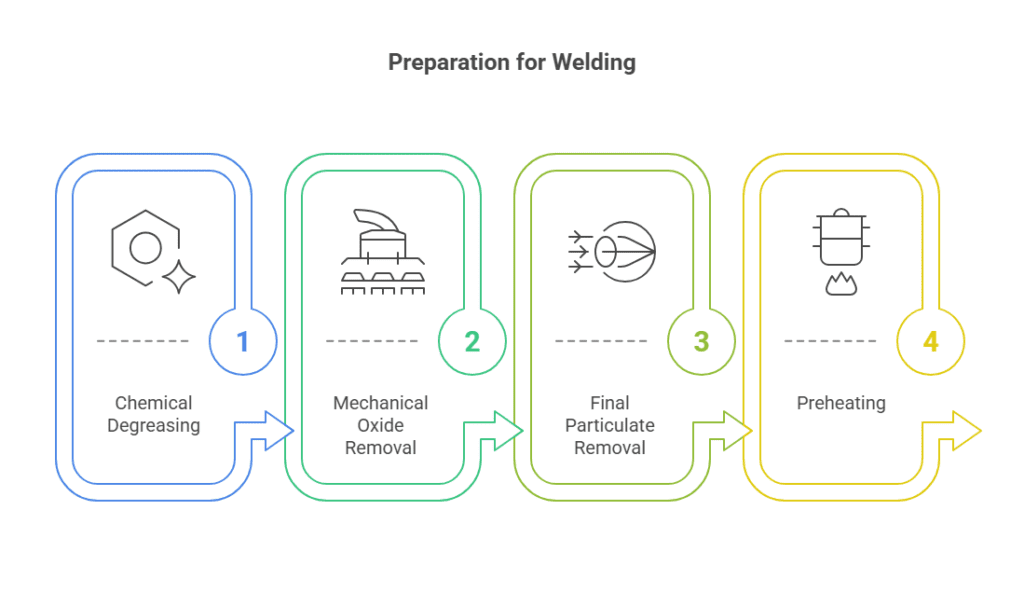
Remove all oils, greases, and organic contaminants using acetone or specialized aluminum cleaners. Apply the solvent with clean, lint-free cloths, working in one direction.
Change cloths frequently to avoid redistributing contaminants. Allow the surface to dry completely before proceeding. Never use chlorinated solvents, as they can cause weld porosity.
Use a stainless steel wire brush dedicated exclusively to aluminum work. Brush in one direction with moderate pressure to remove the oxide layer.
For critical applications, use a carbide burr or file to remove material to a depth of 0.005 inches. The oxide layer reforms within minutes, so weld immediately after cleaning.
Blow the joint area with clean, dry compressed air at 30-40 PSI. Hold the air nozzle at a 45-degree angle to push particles away from the weld zone.
Wipe the area with isopropyl alcohol on a clean cloth. This final cleaning removes any remaining dust or brush particles.
Preheat thick sections over 0.25 inches to 200-300°F. Use temperature-indicating crayons to monitor heat levels accurately.
Apply heat evenly across the entire part using an oxy-fuel torch with a neutral flame. Maintain preheat temperature throughout the welding process. Excessive preheating above 400°F can reduce mechanical properties.
TIG welding uses a non-consumable tungsten electrode to create the arc, with the welder manually feeding a separate filler rod into the weld puddle. This separation of the heat source from the filler material provides the operator with unparalleled control over every aspect of the weld, including heat input, travel speed, and filler metal deposition.
MIG welding uses a continuously fed consumable wire that acts as both the electrode and the filler metal. The wire is fed through a welding gun, making the process semi-automatic and significantly faster than TIG. The process works well for thicker sections above 1/8 inch.
| Feature | TIG Welding | MIG Welding |
|---|---|---|
| Heat Input Control | Excellent – Variable amperage | Good – Fixed by wire speed |
| Deposition Rate | 1-3 lbs/hour | 3-8 lbs/hour |
| Minimum Thickness | 0.020 inches | 0.125 inches |
| Porosity Control | Superior | Good |
| Skill Required | High | Moderate |
| Equipment Cost | $1,500-3,000 | $800-2,000 |
| Best Applications | Repairs, thin sections | Production, thick sections |

For cast aluminum, the choice is almost always between a 4xxx series (aluminum-silicon) and a 5xxx series (aluminum-magnesium) alloy.
ER4043
ER4043 contains 5% silicon and remains the most versatile filler for cast aluminum. This alloy provides good fluidity and minimal shrinkage during solidification.
Use 4043 for general-purpose welding of 3xx.x series castings. ER4043 is the required choice for any component that will experience sustained service temperatures above 150°F (65°C).
ER4047
ER4047 contains 12% silicon, providing superior fluidity compared to 4043. This higher silicon content reduces hot cracking in difficult-to-weld castings.
The alloy works exceptionally well for die castings when welding is necessary. The extra silicon helps overcome contamination issues. However, the higher silicon content slightly reduces ductility.
ER5356
This alloy contains approximately 5% magnesium and provides significantly higher as-welded tensile strength, shear strength, and ductility compared to ER4043. It is the mandatory choice for welding high-magnesium 5xx.x series base metals to avoid the formation of brittle magnesium-silicide compounds.
ER5356 provides a close color match after anodizing, whereas a 4043 weld will turn a dark gray or black, making the repair highly visible.
Allow welded castings to cool slowly to room temperature. Cover the part with ceramic fiber blankets to reduce cooling rates.
Rapid cooling can induce residual stresses and distortion. For smaller applications, place the part in vermiculite or dry sand. Monitor temperature decline to ensure it doesn’t exceed 50°F per hour.
Heat the welded casting to 650°F and hold for 1 hour per inch of thickness. Use a programmable furnace to control heating rates to 100°F per hour.
The stress relief temperature sits below the solution treatment range. This preserves the base metal properties while reducing residual stresses by 80-90%. Cool the part in the furnace at rates not exceeding 50°F per hour.
Even with careful procedure, defects can occur. The most common defects in cast aluminum welding are porosity and cracking.
Porosity appears as small holes or voids within the weld metal. In cast aluminum, porosity often results from hydrogen absorption or trapped gases.
Hot cracking occurs during solidification when thermal stresses exceed the metal’s strength. Cracks typically appear along the weld centerline or in the heat-affected zone.
Incomplete fusion creates weak bonds between the weld and base metal. This defect often occurs when welding thick sections or using insufficient heat input.

