The main difference between investment casting and metal 3D printing is how parts are formed. Investment casting creates metal parts by pouring molten metal into wax-based molds, while metal 3D printing builds parts layer-by-layer using digital designs. 3D printing offers faster prototyping and geometric freedom; casting delivers better surface finish and material strength.

Investment casting is a precision manufacturing process where molten metal is poured into a ceramic mold formed from a wax model. After the wax is melted and drained, the mold is filled with metal to produce complex, high-detail components.
Molten wax is injected into the mold cavity to produce a wax pattern. Once solidified, these patterns are removed from the mold. Multiple wax patterns are then assembled onto a central wax runner system, forming a “tree” or cluster.
The wax tree assembly is repeatedly dipped into a ceramic slurry and then coated with fine ceramic sand. Each layer is allowed to dry before the next is applied. This process is repeated typically 6 to 9 times, building up a robust ceramic shell around the wax patterns.
Once the ceramic shell has cured and hardened sufficiently (often after 24 to 36 hours of drying), the wax inside is removed. This is commonly done using a steam autoclave, where high pressure and steam heat melt the wax out of the ceramic shell, leaving a hollow mold cavity.
The hollow ceramic shell is fired in a high-temperature oven, typically around 1000∘C to 1100∘C (1832∘F to 2012∘F). Molten metal of the desired alloy is then poured into the preheated ceramic mold, filling the cavity previously occupied by the wax patterns.
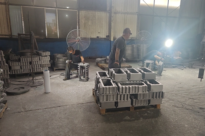
After the molten metal has solidified and cooled sufficiently, the ceramic shell is broken away from the metal casting. This is typically achieved using methods like vibration, water jets, or manual hammering. The individual metal parts are then cut from the central runner system (the metal “tree”) using saws or abrasive cut-off wheels.
The cast parts undergo various finishing operations. These often include removing the gate stubs (where the parts were attached to the runner) by grinding or machining.
Metal 3D printing builds parts layer by layer directly from digital files without requiring molds or tooling. This additive manufacturing technology produces complex geometries impossible with traditional methods.
A 3D model of the part is created using CAD software and then converted into a format the DMLS machine can interpret, typically an STL (Standard Tessellation Language) file. This file is then “sliced” into numerous thin cross-sectional layers.
The build chamber of the DMLS machine is prepared, which includes filling it with an inert gas (e.g., argon or nitrogen) to prevent oxidation of the metal powder at elevated temperatures. The build platform is leveled, and the selected metal powder is loaded into the machine’s reservoir.
A recoater blade or roller spreads a thin, uniform layer of fine metal powder (typically 20 to 50 micrometers thick) across the build platform.
The printer spreads a thin powder layer across the build platform. A high-powered laser (200-1,000 watts) selectively melts the powder according to the programmed pattern. The platform lowers by one layer thickness, and the process repeats until completion.
Once the build is complete, the part, encased in loose powder, is allowed to cool within the build chamber. The build platform is then removed, and the part is excavated from the surrounding unfused powder.
Excess powder is removed from the part (and can often be recycled). Support structures, which are often required to anchor the part to the build plate and support overhanging features during printing, are then removed.
| Feature | Investment Casting | Metal 3D Printing (DMLS/SLM) |
|---|---|---|
| Design Complexity | High, good for intricate shapes | Very High, excels with internal features, lattices |
| Lead Time (Prototypes) | Moderate to Long (weeks, even with 3D printed patterns) | Short (days to a week) |
| Lead Time (High Volume) | Short per part (after tooling) | Moderate to Long (per part, build time is a factor) |
| Tooling Cost | Very High (for injection mold) | Negligible (tool-less) |
| Material Cost (Per Part) | Low to Moderate (bulk alloys) | High to Very High (specialized powders) |
| Cost (Low Volume) | High (due to tooling amortization) | Moderate to High (driven by material/machine time) |
| Cost (High Volume) | Low (economies of scale) | High (less scalable cost reduction) |
| Max Part Size | Very Large capable | Small to Medium (limited by build chamber) |
| Typical Surface Finish (As-Built) | Good (e.g., Ra 3.2-3.8 µm) | Fair to Good (e.g., Ra 6-10 µm), layer lines visible |
| Mechanical Strength (General) | Excellent, isotropic | Good to Excellent, can be near-isotropic post-treatment |
| Material Range | Very Wide (most castable alloys) | Wide, but more limited than IC |