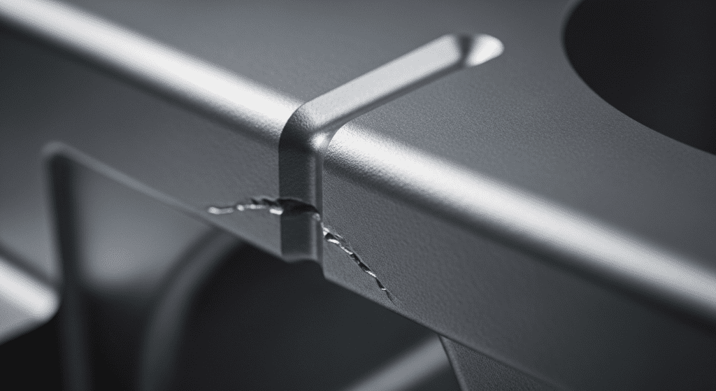
A cold shut is one of the most common defects in die casting that can ruin your parts. It happens when two streams of molten metal meet but don’t fuse together properly, creating a visible line or gap on the surface. This defect weakens the part and often leads to rejection during quality control.
The key insight is that cold shuts are completely preventable with the right process controls. The answer to preventing them lies in understanding what causes these temperature drops and how metal flows through your die.

Low melt temperature is the primary cause of cold shut defects. When molten metal enters the die cavity below optimal temperature, it begins solidifying too quickly.
This premature cooling prevents proper fusion when metal streams converge. The metal lacks sufficient heat energy to maintain fluidity throughout the entire cavity fill process.
Cold dies extract heat from molten metal too rapidly. This accelerates solidification before the cavity completely fills.
Die temperature must be high enough to keep metal fluid during injection. Insufficient preheating or poor temperature maintenance between shots creates conditions for cold shut formation.
Speed matters critically in die casting. Slow injection allows more time for heat loss during cavity filling.
Extended fill times mean the first metal entering the die has more time to cool before meeting later streams. This temperature differential prevents proper fusion at flow convergence points.
Low pressure reduces metal velocity through gates and runners. This extends fill time and increases heat loss.
Adequate pressure ensures rapid cavity filling before significant cooling occurs. Pressure also helps force metal streams together for better fusion at meeting points.
Complex part geometries create longer metal travel distances. Each additional inch of flow path increases heat loss opportunity.
Tortuous paths with multiple direction changes slow metal flow further. This compounds the cooling problem and raises cold shut risk in distant cavity sections.
Poor gate placement forces metal to travel unnecessary distances. Multiple gates must be positioned to minimize flow length to all cavity areas.
Runner design affects metal velocity and heat retention. Undersized runners restrict flow and increase fill time, while oversized runners allow excessive heat loss.
Trapped air opposes incoming metal flow. This resistance slows filling and can deflect metal streams.
Insufficient venting creates back pressure that disrupts normal flow patterns. Metal streams may meet at unintended angles or locations, preventing proper fusion.
Overflows serve dual purposes: removing cold metal and providing additional venting. Improperly designed overflows fail to capture the coldest metal from flow fronts.
This cold metal remains in the casting, creating cold shut defects where flows converge. Overflow placement must consider flow patterns and convergence zones.
Different alloys have varying fluidity characteristics. Low-fluidity alloys are more prone to cold shut defects.
Alloy chemistry affects solidification temperature range and flow behavior. Silicon content in aluminum alloys, for example, significantly impacts fluidity and cold shut susceptibility.
Oxide films on metal surfaces prevent proper fusion between converging streams. These films act as barriers even when metal temperature is adequate.
Contamination from die lubricants or other sources creates similar fusion barriers. Clean melt handling and proper die preparation are essential for preventing these issues.

Maintain melt temperature at the high end of the recommended range. This provides maximum fluidity and fusion capability.
Monitor and control die temperature continuously. Use thermocouples and automatic temperature control systems to maintain consistent conditions. Preheat dies thoroughly before production begins.
Optimize injection speed profiles for rapid cavity filling. Use high initial velocity to quickly fill thin sections before cooling begins.
Adjust intensification pressure timing to ensure complete fill and metal compression. This forces converging streams together for better fusion.
Position gates to minimize flow distances to all cavity areas. Use multiple gates when necessary to reduce maximum flow length.
Size runners for optimal flow velocity without excessive heat loss. Consider heated runner systems for challenging applications. Design smooth transitions to maintain metal velocity.
Provide adequate venting in all areas where air might trap. Focus on convergence zones where flows meet.
Position overflows to capture cold metal from flow fronts. Size them sufficiently to remove all potentially cold material before flows converge in the casting.
Choose alloys with good fluidity characteristics when possible. Higher silicon content improves fluidity in aluminum alloys.
Maintain consistent alloy composition through careful melt management. Monitor and adjust chemistry as needed to ensure optimal flow properties.
Implement rigorous melt cleaning procedures. Use degassing and filtration to remove oxides and inclusions.
Minimize turbulence during metal transfer to prevent oxide formation. Cover melts when possible and use proper fluxing techniques. Clean dies regularly to prevent contamination buildup.

