The main difference between sand casting and centrifugal casting is how the mold and metal interact. Sand casting uses static sand molds and gravity to form parts, while centrifugal casting spins a mold rapidly to force molten metal outward. Centrifugal casting produces denser, more precise parts with fewer impurities.

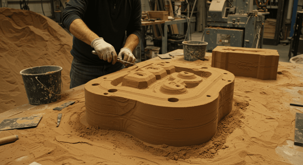
Sand casting is a metal casting process that uses a mold made of sand to form metal parts. The process involves packing sand around a pattern, removing the pattern, and pouring molten metal into the cavity. After cooling, the sand mold is broken to retrieve the cast object.

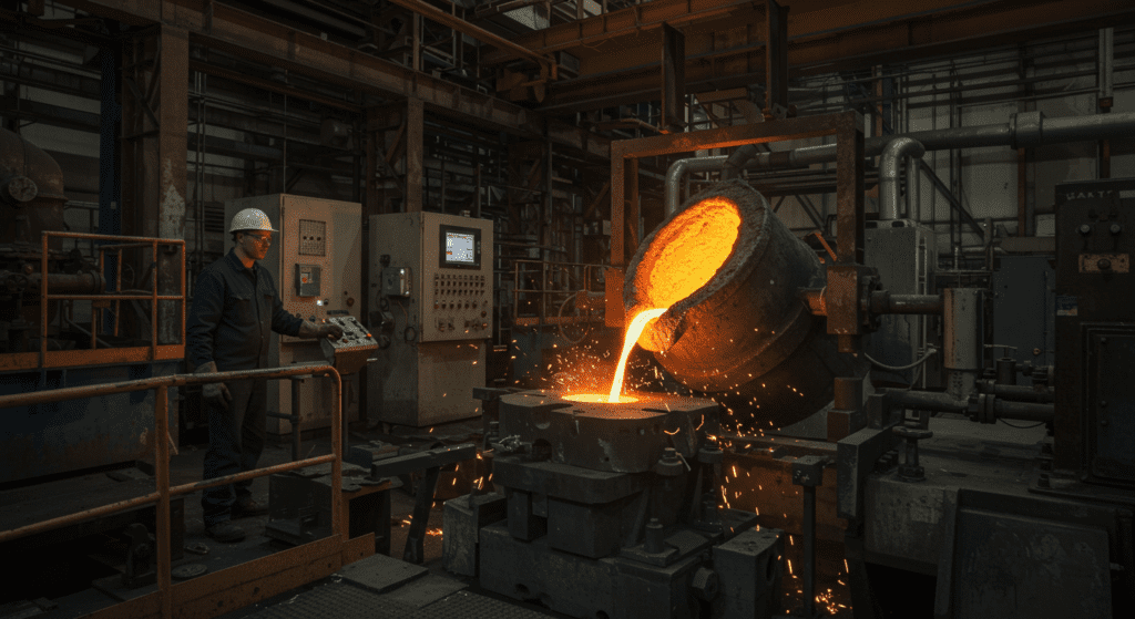
Centrifugal casting is a metal casting process that uses high-speed rotation to distribute molten metal inside a mold. The centrifugal force pushes impurities to the center, allowing denser metal to form a strong, defect-free outer shell. It is commonly used to manufacture cylindrical components like pipes and bearings.
| Aspect | Sand Casting | Centrifugal Casting |
|---|---|---|
| Mold Preparation | Create expendable sand molds for each part. Process takes 30-60 minutes per mold | Use permanent metal or graphite molds. Initial setup takes days but molds last for thousands of parts |
| Mechanical Properties | Lower overall strength and ductility. Porosity of 2-5% is common | Uniform properties throughout. Porosity under 1% due to centrifugal force |
| Types of Metals | Works with iron, steel, aluminum, copper alloys, magnesium, and zinc | Best for aluminum, copper, steel, and stainless steel. Limited success with reactive metals |
| Costs | Low tooling cost ($500-$5,000). High labor cost per part | High tooling cost ($10,000-$100,000). Low labor cost per part after setup |
| Typical Applications | Engine blocks, valve bodies, pump housings, decorative items, prototypes | Pipes (6 inches to 10 feet diameter), cylinder liners, bearing housings, brake drums |
| Production Volume | Economical for 1-1,000 parts. Suitable for prototypes and small batches | Requires minimum 100 parts for cost efficiency. Ideal for 1,000-100,000 parts annually |
| Dimensional Accuracy | Tolerances of ±0.030 inches typical. Surface finish of 250-500 microinches | Tolerances of ±0.010 inches achievable. Surface finish of 60-125 microinches |
| Part Complexity | Handles complex geometries, undercuts, and irregular shapes | Limited to cylindrical and symmetrical shapes. Cannot produce complex internal features |
| Wall Thickness | Minimum 0.125 inches for aluminum, 0.1875 inches for iron | Uniform walls from 0.25 to 5 inches. Thickness controlled by rotation speed |
| Lead Time | Parts ready in 2-4 weeks including pattern making | First parts in 6-8 weeks due to mold fabrication. Subsequent parts in days |

